
In modern building construction and interior design, installing equipment such as air conditioners, ventilation systems, and dehumidifiers inside ceilings has become a common practice that balances aesthetic appeal with functionality. However, this concealed installation method also presents a significant risk that cannot be overlooked: water leakage. If the drainage system malfunctions, the consequences can range from damaging the ceiling and staining decorative surfaces to destroying floors, walls, and even electrical wiring. Repair costs often exceed the value of the equipment itself by several times. Therefore, when designing condensate drainage and leak prevention for concealed ceiling-mounted equipment, it is essential to adopt a proactive safety mindset focused on “prevention.”
I. Analysis of the Advantages and Disadvantages of Two Mainstream Drainage Solutions
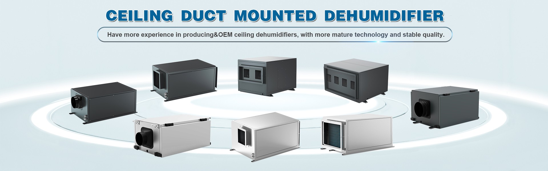
The core of condensate drainage for ceiling-mounted equipment lies in smoothly transporting water from a higher elevation (inside the ceiling) to a lower elevation (floor drain, drainpipe, or outdoors). Currently, two primary technical approaches are used: gravity-fed drainage and pump-assisted drainage.
Gravity-fed drainage relies on natural gravity, using pipes with a certain slope to allow condensate to flow out on its own. Its greatest advantages are simple structure, reliable operation, no need for additional power, and no risk of pump failure. However, it has strict installation requirements: the drain pipe must maintain a continuous downward slope, and the space within the ceiling is often insufficient when the piping is too long. Furthermore, when the piping has many bends or long horizontal sections, it is prone to accumulating dirt and fostering algae growth, which can eventually lead to blockages.
Pump-assisted drainage uses a small pump to first lift the condensate a certain height before allowing it to drain by gravity. Its advantage lies in significantly reducing the requirements for installation slope, allowing for flexible routing of the drain pipes, making it particularly suitable for scenarios with limited ceiling space or distant drainage points. However, the drawbacks are equally evident: the pump is susceptible to mechanical failure, generates some operational noise, and has a limited lifespan. Furthermore, if the pump fails or the drain pipe becomes blocked, water will rapidly accumulate in the drip pan and overflow.
A clear understanding of the inherent characteristics of both solutions is essential for selecting an appropriate drainage method. There is no absolutely perfect solution; the choice depends solely on whether it suits the on-site conditions.
II. Principles of Core Components in Active Leak Prevention
Relying solely on the unobstructed drainage path is unreliable; a truly effective safety system must incorporate multiple monitoring and intervention measures. The following components form the foundation of active leak prevention:
The dual-float switch is a water level monitoring device located within the drip tray. It consists of two independent floats: the low-level float serves as the standard trigger for drainage, activating the pump or issuing a drainage command when the water level rises normally; The high-level float serves as the “last line of defense.” If the water level abnormally rises to a dangerous height, the high-level float immediately triggers a forced shutdown and outputs an alarm signal. The dual-float design separates the “operating water level” from the “alarm water level,” ensuring normal drainage functionality while providing clear fault redundancy.
Electronic water leak alarms are typically installed at the lowest point of a drip pan or within a suspended ceiling. Utilizing water’s electrical conductivity or capacitive sensing principles, the device immediately emits an audible and visual alarm when the sensor comes into contact with liquid. It can also output a dry contact signal to integrate with building automation systems or home smart gateways. Modern electronic water leak alarms can also use wireless transmission to push leak notifications to users’ mobile phones. The key lies in the careful placement of the detector’s probe—it should not be positioned where water is certain to flow, but rather in sensitive areas where a leak would first appear.
An overflow-proof tray is a passive mechanical protection device. It consists of an oversized tray placed over the equipment’s drip pan, with the tray’s edges raised to a certain height to form a “bowl-shaped” container. When the internal drip tray overflows due to blockages, pump failures, or other causes, the overflowing water is collected by the anti-overflow tray and drained through a separate secondary drain outlet or floor drain on the tray. A more advanced design incorporates water leakage sensors on the anti-overflow tray as well, providing dual monitoring.
These three types of components respectively fulfill the protective functions of “control, detection, and containment,” and none can be omitted.
III. Establishing a Proactive Leak Prevention Safety System
A truly reliable leak prevention solution is not simply a matter of stacking components, but rather establishing a well-structured, interconnected safety system. This can be approached from the following four levels:
Level 1: Optimize Basic Drainage Design. Whether using gravity drainage or a lift pump, ensure the drip tray itself has a reasonable slope to allow condensate to flow smoothly toward the drain inlet. Drain pipes should be made of anti-aging materials with smooth inner walls, and the number of joints should be minimized. For gravity drainage, the slope should not be less than 1%, and cleaning ports should be installed at regular intervals; for lift pump drainage, the pump’s intake strainer should be cleaned regularly.
Level 2: Configure dual float switches linked to the system. Connect the low-level float to the equipment’s drainage control logic (or the lift pump’s start/stop control), and connect the high-level float to the equipment’s main power control circuit. This means that once the water level reaches the high-level float, the equipment must shut down immediately, cutting off the water and steam supply while simultaneously triggering an alarm signal. A scenario where “the equipment continues to operate while condensate keeps being generated” must not be allowed.
Level 3: Deploy a distributed leak detection network. Install electronic water leak detectors at critical locations within the ceiling cavity—specifically beneath the equipment’s drip pan, inside the overflow containment tray, beneath drain pipe connections, and near the lowest access panel in the ceiling. These detectors should feature a centralized alarm function, ensuring that a trigger at any point clearly displays the leak location on the control panel. For residential users, battery-powered wireless leak sensors paired with a smart gateway can be used to enable mobile notifications.
Layer 4: Implement physical disaster recovery measures. The overflow tray serves as the final physical barrier and must not be omitted. The tray’s surface area should cover the equipment’s footprint and extend outward, with a flange height of at least 3–5 centimeters. The tray should be made of stainless steel or corrosion-resistant material and feature a secondary drain at its lowest point, leading directly and independently to a visible drainage point (such as a mop sink or floor drain), without sharing the same drainage line as other pipes. This ensures that even if all active measures fail, water will be contained within the tray and drained away on its own, preventing it from overflowing into the ceiling cavity.
IV. Regular Inspections and Maintenance Must Not Be Neglected
Even the most sophisticated system requires periodic verification. It is recommended to conduct a “simulated leak test” every six months: slowly pour a small amount of clean water into the drip pan to observe whether drainage is unobstructed, whether the dual float switches respond sensitively, and whether the high-level float switch shuts down the system normally. At the same time, check the water leak alarm’s batteries and sensors for signs of oxidation. For lift pumps, listen for any abnormal operating noises and clean out sludge and algae from the pump body and piping.
The greatest risk of concealed ceiling-mounted equipment lies in its “invisibility.” Shifting leak prevention design from “reactive repair” to “proactive prevention” relies on a comprehensive system that integrates gravity or mechanical drainage, dual-float control, electronic sensing alarms, and a physical disaster-tolerant base tray. While each component may seem like a simple technology on its own, when properly integrated and organized into distinct layers, they can achieve extremely high reliability within a limited budget.
After all, the cost of repairing a single leak far exceeds the investment in a proactive leak prevention system. Prevention is the truly wise choice.
 vivienhu0427@hotmail.com
 +86 15958041362
 vivien@hzfreeair.com